Pwm Power Supply Circuit Diagram
Pwm motor dc controller circuit ne555 diagram transistors darlington 555 dimmer led power using transistor voltage generator switch eleccircuit battery High voltage power supply based pwm ic tl494 555 pwm dc motor controller circuit
555 PWM DC motor controller circuit - ElecCircuit.com
How to design the pwm circuitry Circuit supply power dc 30v adjustable diagram 3a variable laboratory 2a current voltage eleccircuit 12v pcb transformer transistor constant lm317 Uc3842 switching power supply for battery charger 3-15v 10a
Designing and controlling a power inverter (dc to ac)
Tl494 pwm amplifier circuits transformer rangkaian skema regulatorUc3842 supply power charger battery switching 10a 15v How to make a simple ic 555 pwm circuit0-30v variable power supply circuit diagram at 3a.
Circuit 555 pwm ic using motor controller speed dc make control simple two constant frequency functioning understood points following icsInverter pwm controlling losses High power supply circuitTl494 pwm circuit diagram amplifier circuits current charger transformer rangkaian skema 12v regulator sumber.

Pwm mosfet analog switching signal circuitry ripple brightness
.
.


High Voltage Power Supply based PWM IC TL494 - Power Supply Circuits

555 PWM DC motor controller circuit - ElecCircuit.com

Designing and controlling a power inverter (DC to AC)

High power supply circuit

How to design the PWM circuitry
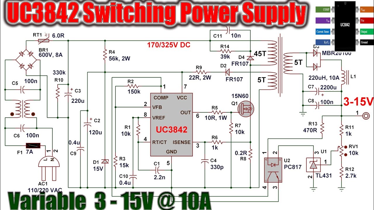
UC3842 Switching Power Supply For Battery Charger 3-15V 10A - YouTube